


Logic Gates & Circuits
Logic Gates & Circuits
Lesson Objectives
- Logic gates (NOT, AND & OR)
- To apply the concept of logic gates to analyse and build logic circuits
- To Analyse the logic circuit of half adder
- To design a logic circuit
- Using these logical operators used in programming
What are Logic Gates?
- Logic gates are the building blocks of electronic circuits that are used in computer components like memory and other controlling devices.
- Logic gates work on the principle that the binary digit 1 represents the ON or TRUE state and 0 represents the OFF or FALSE state.
Why Do We Need Logic Gates?
- A computer understands binary language. So, the components of the computer contain logic gates, which work on the binary system.
- The data and instructions are processed in binary form.
Logic Gates

Truth Table

- A truth table is used to denote the different outputs of the logic gates or circuit with respect to different inputs.
- A NOT gate has one input and, hence, has 2^1 possible combinations.
- The OR and AND gates have two inputs and 2^2 output combinations are possible.
- Logic circuits can also have more than two inputs.
- For n inputs, the number of possible output combinations is 2^n.
Logic Gates: NOT Gate

- The output of the NOT gate is complementary to the input.
Logic Gates: AND Gate

- The output of an AND gate is 1 only when both the inputs are 1.
Logic Gates: OR Gate

- The output of an OR gate is 1 when any one of the inputs is 1.
What are Logic Circuits?

- Logic gates are combined to form logic circuits that are responsible for a unique function, for example, controlling the various mechanisms of an oven such as temperature, timing, etc.
- Let us consider the given circuit. We will analyse the circuit and determine its truth table. It can be noted that there are three inputs; hence, 2^3=8 possible binary combinations.
Analyzing Logic Circuits: Step 1
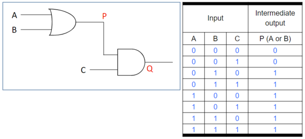
- To reduce errors, the circuit is split into two parts with an intermediate output P and final output Q.
- P is the output of the first OR gate with inputs A and B. P is true when either A or B is true.
Analyzing Logic Circuits: Step 2

- Q is the output of the AND gate with P and C as inputs. Q is true only when both P and C are true.
Analyzing Logic Circuits: Step 3

- The intermediate output is removed to obtain the final truth table.
- Using the logic circuit, the logic notation of output Q is Q= (A OR B) AND C. Using symbols in logical notation,
Q = (A + B).C
What is a Half Adder

- The Arithmetic and Logic Unit (ALU) in a CPU uses a half-adder logic circuit for performing binary addition of two bits.
- The input consists of two bits, A and B, and hence, 2^2= 4 input combinations are possible.
Half Adder: Truth Table

- It can be noted that two outputs bits are required to denote sum and carry.
- The output Sum(S) is 1 when both inputs A and B have different values.
Half Adder: Realizing Logic Circuit
- It can be noted that two outputs bits are required to denote sum and carry.
- The output Sum(S) is 1 when both inputs A and B have different values.
- S is true under two conditions:
A is false and B is true ((NOT A) AND B) A is true and B is false (A AND (NOT B)) Sum S = ((NOT A) AND B) OR (A AND (NOT B)) S = ((¬A) ^B) ˅(A^(¬B))
Half Adder: Logic Circuit
- The output carry is 1 only when both the inputs are 1 and, hence, it can be realised using an AND gate.
C=A AND B = A^B

S = ((¬A) ^B) ˅(A^(¬B))
C=A AND B = A ^B
Designing a Logic Circuit

- A safety system has three inputs K, L and M. An alarm Y, sounds if input K is ON and L is ON; or if input L is ON and M is OFF.
- The logical statement for the function of Y is Y= 1 if (K=1 AND L=1) OR (L=1 AND M=NOT 1).
Designing a Logic Circuit: Truth Table

The truth table can be cross-checked with a logic circuit and logic statement
Y= 1 if (K=1 AND L=1) OR (L=1 AND M=NOT 1)
Related Worksheets:

Become a Help Teaching Pro subscriber to access premium lessons
Unlimited premium lessons Unlimited premium printables Unlimited online testing
- Already a Pro subscriber? Log in for access
- Browse free lessons
- Go back to previous page